This is an introduction to authentic Type 89 Mortar Shells. The Type 89 Mortar Shell was the dedicated round designed for use with the Type 89 Heavy Grenade Discharger. According to documents from the time of provisional adoption1, the shell was filled with 150g of explosive and had a complete weight of 800g. In terms of effect, detonation produced approximately 100 fragments with a lethal radius of 10 meters.
In this article, I compare three deactivated authentic examples.
The example on the left, with the yellow band, is on loan from Dekunobo. Manufactured in Shōwa 16 (1941), it shows no rifling marks on the driving band, suggesting it is likely an unfired example.
The example on the right is somewhat older, manufactured in Shōwa 8 (1933). The warhead is expanded and has a larger diameter than a standard example, and the body also flares outward. According to someone knowledgeable on the subject, this type of deformation is seen on examples that were fired as training rounds. Rifling marks are visible on the driving band. It should also be noted that this is the only example where the stamped serial numbers on the components do not match — the warhead bears a different stamp from the rest.
The center example was manufactured in Shōwa 17 (1942). Rifling marks are visible on the driving band, suggesting it has been fired. However, there is no expansion visible on the warhead or body. Furthermore, the serial numbers on all components match, suggesting the parts are in their original combination. This example may have been fired without an explosive charge.
The details are discussed in the latter half of this article, but it seems most reasonable to interpret the example on loan from Dekunobo as an authentic Type 89 Mortar Shell intended for combat use, while the two examples in my own collection are most likely Type 94 Practice Rounds intended for training.
Markings Comparison
First, I examine the markings on each part to identify information such as the period and place of manufacture.
Manufactured in July Shōwa 16 (1941), Sagami Army Arsenal
First, I examine the example on loan from Dekunobo in detail.
The fuze bears the text “八八式” indicating the Type 88 Small Instantaneous Fuze, along with the markings “昭十七 4”, a crossed-cannon mark, and “阪”, reading from right to left. “昭十七 4” indicates manufacture in April 1942, while the crossed-cannon mark and “阪” indicate that it was manufactured at the Osaka Army Arsenal.
The body bears the markings “昭十六 7”, an arsenal mark, and a circled “H” — or what could also be read as a vertically oriented katakana “エ” (e) — reading from right to left. “昭十六 7” indicates manufacture in July 1941, and the arsenal mark is that of the Sagami Army Arsenal.
The body also bears the circled hiragana “ろ” (ro) and the number “4757”.
The base also bears the circled hiragana “ろ” (ro) and the number “4757”.
Manufactured in May Shōwa 8 (1933), Osaka Army Arsenal
Next, I examine the example with the expanded warhead.
The fuze bears the text “八八式”, along with “昭八 5”, a crossed-cannon mark, and “阪”. These markings indicate that it was manufactured in May 1933 at the Osaka Army Arsenal (known at the time as the Osaka Factory of the Army Arsenal).
The warhead bears an “×”-shaped mark that resembles a simplified version of the crossed-cannon symbol, along with a number reading “M923”.
The body bears the marking “昭八 5”, indicating manufacture in May 1933. Although surface deterioration makes them difficult to read, a crossed-cannon mark and what appears to be “阪” are also visible. A circled chevron-shaped marking is also present, though its meaning is unclear — it may possibly be a civilian contractor’s mark.
The body and driving band both bear the same number, “M647”.
No serial number is visible on the base; only an “×” or cross-shaped marking is present. Based on its appearance, it may be the same marking as the “×”-shaped stamp found on the warhead.
Manufactured in April Shōwa 17 (1942), Nagoya Army Arsenal
Finally, I examine the example manufactured in 1942.
The fuze bears the text “八八式”, along with “昭十三 3”, a mark depicting a circle within a star, “東”, and “セ”. It should be noted that unlike the other two examples, the position of the markings indicating the year and place of manufacture differs on this example.
The circle-within-star mark and “東” suggest a connection to the Tokyo First Army Arsenal. However, the Tokyo Arsenal was reorganized into the Tokyo First Army Arsenal in 1940, while this fuze was manufactured in 1938. It therefore seems more natural to conclude that this example was produced at the Tokyo Arsenal prior to the reorganization.
The meaning of the “セ” (se) marking remains unclear.
The warhead bears the number “ソ8899” (so 8899).
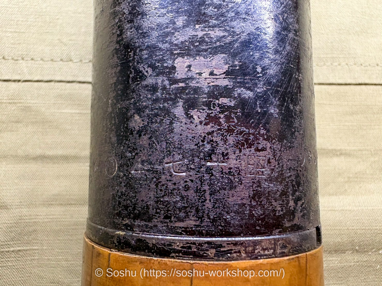
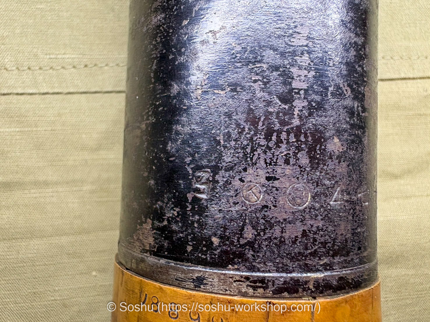
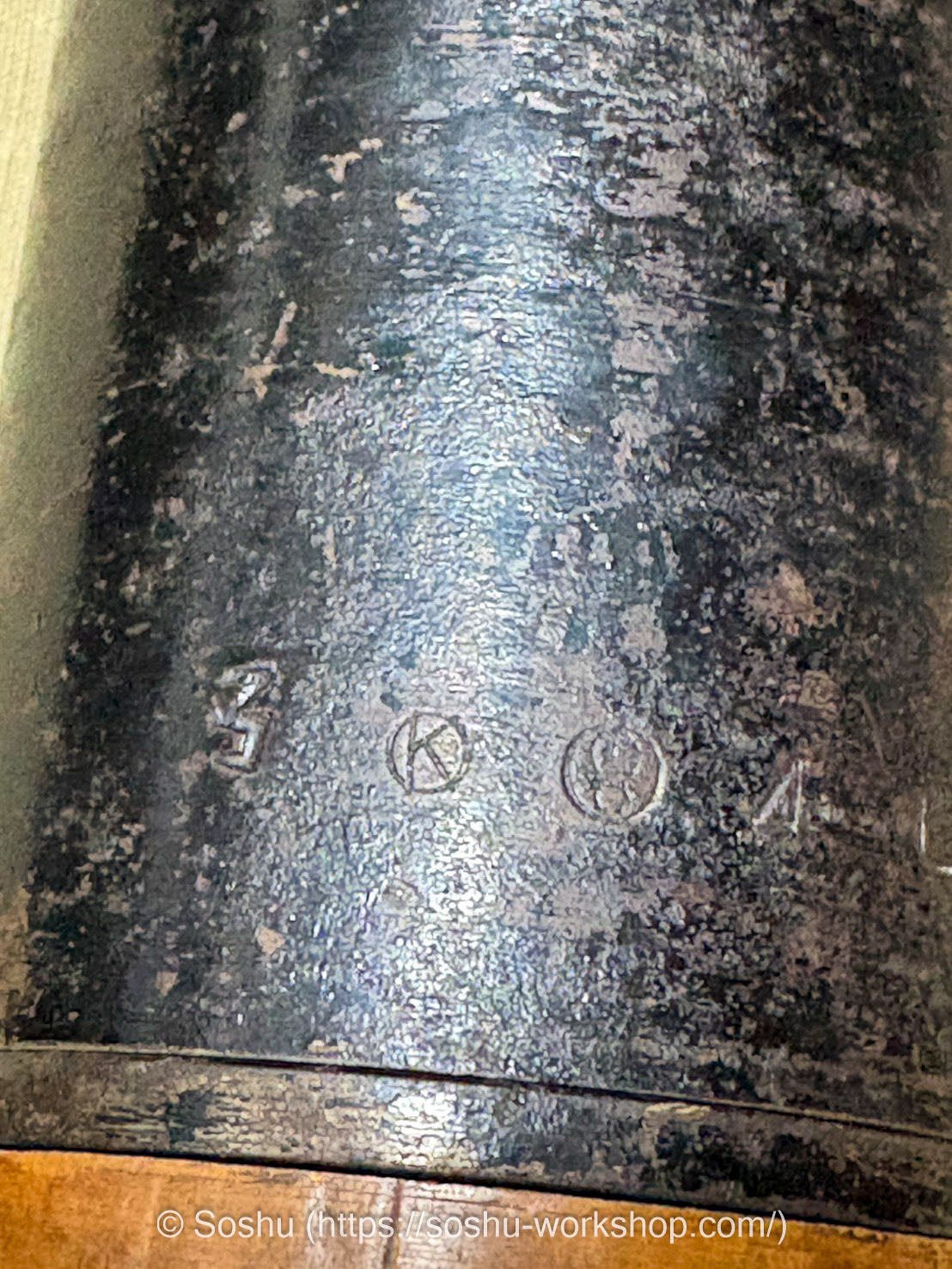
The body bears the marking “昭十七 4”, indicating manufacture in April 1942, along with the Nagoya Army Arsenal mark — a large and small circle arranged within a circle — a circled “K”, and the character “名”.
The left half of the “名” stamp is faint and difficult to read in isolation, but given the presence of the arsenal mark, it can reasonably be interpreted as part of “名” for Nagoya Army Arsenal.
The meaning of the circled “K” is unclear, but it may be an identifying mark for a civilian contractor.
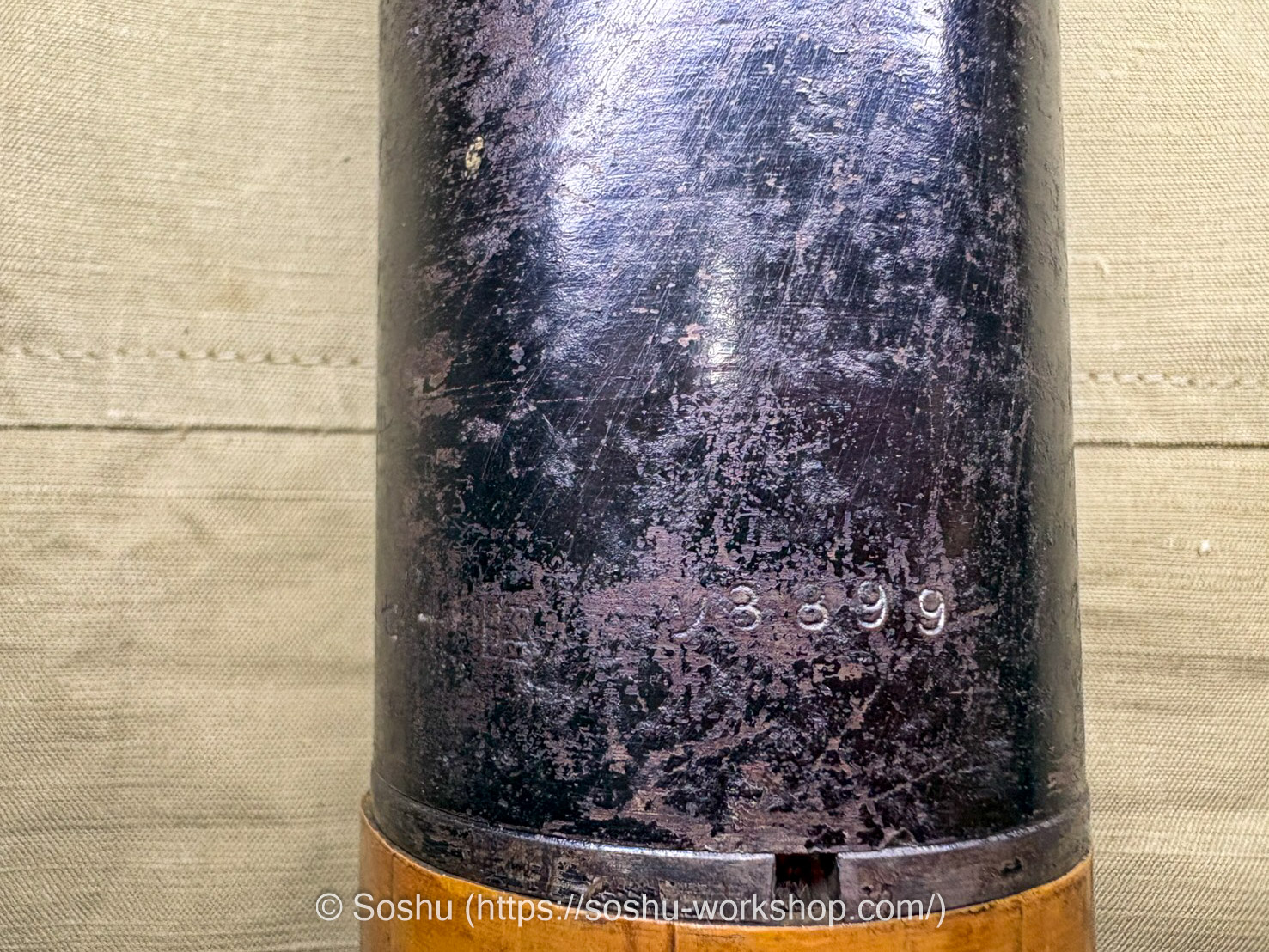
The body and driving band both bear the number “ソ8899” (so 8899), shared with the warhead.
The base also bears the number “ソ8899” (so 8899). As the numbers on the warhead, body, driving band, and base all match, it can be concluded that the components of this shell are in their original combination.
Component Disassembly
Next, I disassemble the Type 89 Mortar Shell to examine its internal structure and individual components.
Manufactured in July Shōwa 16 (1941), Sagami Army Arsenal
First, I examine the example on loan from Dekunobo.
The shell body can be disassembled into three parts: the warhead, body, and base. The fuze attached to the warhead is left-handed (reverse) threaded, but on this example it had seized and could not be removed.
The interior of the base houses the propellant charge used to fire the shell. At the center of the base is a hole for the firing pin to strike, surrounded by eight gas vents. These vents are sealed with a thin copper plate, which is ruptured by the combustion gases upon firing, allowing the gas to escape.
Around the exterior of the base is a copper ring known as the driving band. Upon firing, the driving band engages with the rifling inside the grenade discharger barrel, imparting spin to the shell.
Between the driving band and the base, five small silver circles are visible — these are small screws. As this example is on loan, and given the possibility that removing the driving band might prevent reassembly, I chose not to disassemble it on this occasion.
The holes visible on the side and base of the body were drilled as part of the deactivation process and are not present on original unfired examples.
The interior of the body houses the bursting charge, which is completely separated from the base section containing the propellant.
Pictured here are the warhead and fuze. The part protruding into the interior of the warhead is the fuze’s tail tube, which contains the igniting charge.
The tip of the fuze is designed to be separable, and houses the firing mechanism including the firing pin. On this example, some of those components remained intact.
Manufactured in May Shōwa 8 (1933), Osaka Army Arsenal
Next is the example with the expanded warhead.
On this example, the body and base had seized together and could not be disassembled. Similarly, the fuze had also seized and could not be removed.
However, the notable feature of this example is that the internal components of the fuze remain in an almost complete state. I will take a closer look at these components and examine the operating mechanism in detail later in the article.
Manufactured in April Shōwa 17 (1942), Nagoya Army Arsenal
The final example is in good condition and can be disassembled into four parts: the warhead, body, base, and driving band. The fuze can also be removed.
Unlike the example from Dekunobo, the driving band on this example is slightly flared and does not sit flush against the base. Additionally, while there should be five small screws securing the driving band, three are missing on this example.
When I removed the base for the first time after acquiring this example, one of these screws rolled out from inside the propellant chamber. The previous owner presumably did not know what the screw was for and simply placed it inside the propellant chamber for safekeeping.
The remaining screws were likely lost in a similar manner.
With the driving band removed from the base, this is what it looks like. The small fixing screw described earlier is placed at the center bottom of the photo, giving a sense of just how small a component it is.
The base features gas vents not only on the bottom face but also on the sides. When the propellant burns, the high-pressure combustion gases are expelled laterally through these vents, and the resulting pressure instantaneously forces the copper driving band outward.
This causes the driving band to engage with the rifling inside the grenade discharger barrel, imparting spin to the shell. It is this mechanism that allows the shell to be inserted smoothly when loading from the muzzle, while still reliably engaging the rifling upon firing.
This example has two notches on the lower section of the body. Why these are present only on this example is unclear.
The bottom of the body also bears the number “8899”, though it is somewhat difficult to read.
The fuze body is left-hand threaded and can be removed from the warhead by turning it clockwise.
The tail tube, however, is missing. The upper portion of the fuze could be disassembled, but the internal firing mechanism had been destroyed — it appears to have been crushed and removed as part of the deactivation process.
Type 88 Small Instantaneous Fuze
The fuze used in the Type 89 Mortar Shell is known as the Type 88 Small Instantaneous Fuze. A similarly named Type 88 Instantaneous Fuze also exists, but the version without “Small” is a fuze designed for field artillery shells and is an entirely different item.
The “八八式” stamp on the fuze has led to the Type 89 Mortar Shell occasionally being referred to as the “Type 88 shell”, but this is incorrect. “八八式” refers solely to the name of the fuze; the official designation of the shell itself is the Type 89 Mortar Shell.
Incidentally, the Type 88 Small Instantaneous Fuze was also used in the Type 94 Practice Round (training round) for the Type 89 Heavy Grenade Discharger, as well as the Type 11 Smoke Shell for the Type 11 Infantry Howitzer. A detailed explanation of the structure of the Type 88 Small Instantaneous Fuze can be found in “Handling Precautions of Model 88 Small Super Quick Fuse”.2
The Army Infantry School’s “擲弾筒取扱上の参考” (Reference on the Handling of Grenade Dischargers) contains even more detailed drawings than those found in “Handling Precautions of Model 88 Small Super Quick Fuse”. In this section, I examine the structure of the fuze by comparing these drawings with an authentic fuze manufactured at the Osaka Arsenal in May 1933.
Please note that in the Japanese version of this article, the terminology used follows that of “擲弾筒取扱上の参考” directly. In the English version, some terms have been freely translated as there are no established equivalents, and I ask for your understanding in this regard.
First, I examine the larger components. The upper half of the fuze, which can be unscrewed and removed, is called the “蓋螺” (cap thread), and the lower half is called the “体” (body). The firing pin section at the tip of the fuze consists of four components: the “帽” (cap), “撃針覆” (firing pin cover), “撃針” (firing pin), and “支鐶” (support ring).
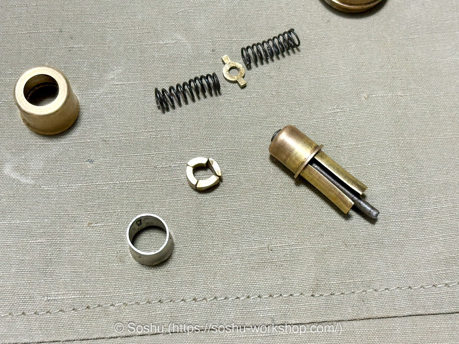
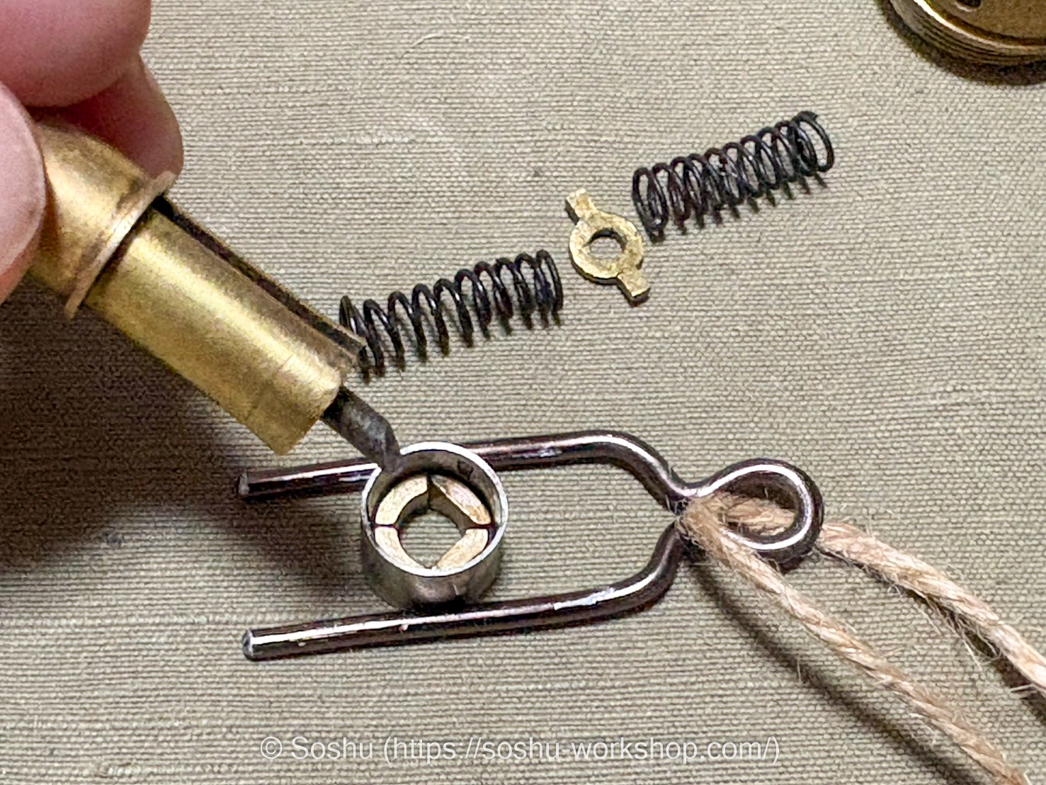
In addition to these, a number of smaller components are incorporated to allow the firing pin to strike the percussion cap. I have arranged these components on top of the drawings for reference. Visible among them are the “加量筒” (increaser tube), “支耳” (support ear), “上部発條” (upper spring), “発條受” (spring seat), “下部発條” (lower spring), and the “遠心子” (centrifugal piece), which plays a critically important role as a safety device.
The centrifugal piece is an extremely small component. Four of them are combined to form a circle and assembled inside the fuze.
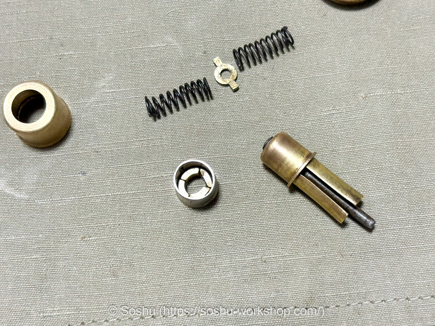
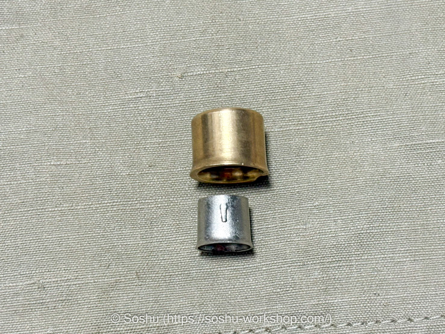
The silver component on the left is the support ear, which has four protrusions around its outer circumference. The brass component is the increaser tube.
Before firing, the increaser tube simply rests on top of the support ear. Upon the shock of firing, however, the support ear is forced into the interior of the increaser tube, causing the protrusions on the support ear to catch on the increaser tube, locking the two together permanently.
This metal fragment was also found inside the fuze. It appears to be a thin copper tube that has been crushed, but I was unable to identify a corresponding part in the drawings.
The origin of this component within the fuze therefore remains unknown.
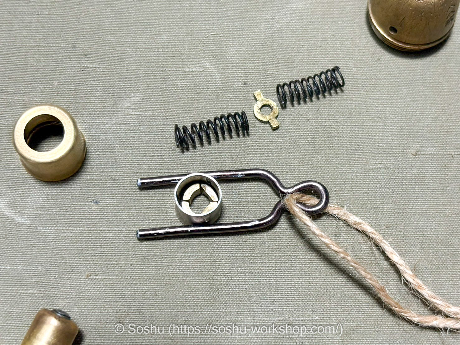
As the structure is difficult to convey through photographs alone, I have arranged the components in their estimated assembly order for clarity.
First, the four centrifugal pieces are combined and arranged in a circle. The support ear is then placed over them to hold the centrifugal pieces together and prevent them from separating.
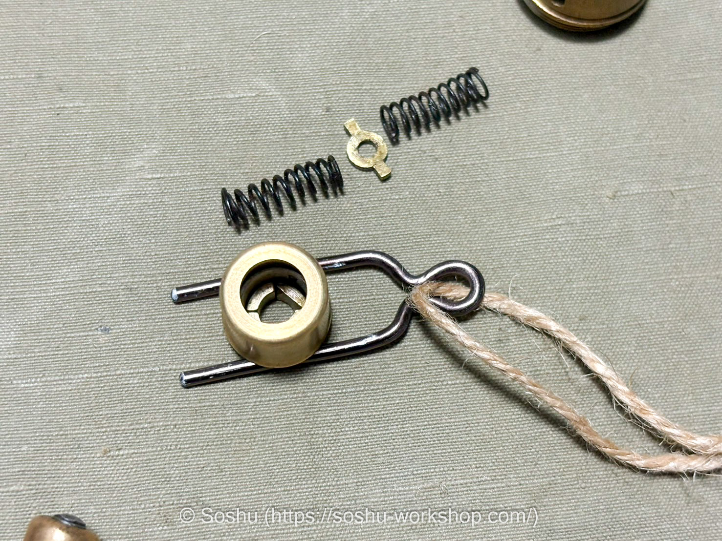
Next, the safety pin is inserted, and the increaser tube is placed over the assembly. Upon firing, inertia applies a downward force to the increaser tube, pushing it toward the support ear. However, with the safety pin in place, the support ear cannot enter the interior of the increaser tube.
The firing pin is then assembled from above. At this stage, the centrifugal pieces restrict the movement of the firing pin, preventing it from advancing and striking the percussion cap.
Even after the safety pin is removed, the firing pin cannot strike the percussion cap as long as the centrifugal pieces remain in their correct position. However, if the support ear enters the interior of the increaser tube for any reason, the restraint on the centrifugal pieces is released, leaving the fuze in a dangerous state where it can fire at any moment.
The condition of the centrifugal pieces cannot be verified from the outside. For this reason, the “Handling Precautions of Model 88 Small Super Quick Fuse” states that the safety pin must only be removed immediately before loading, and that a safety pin once removed must never be reinserted into the fuze.
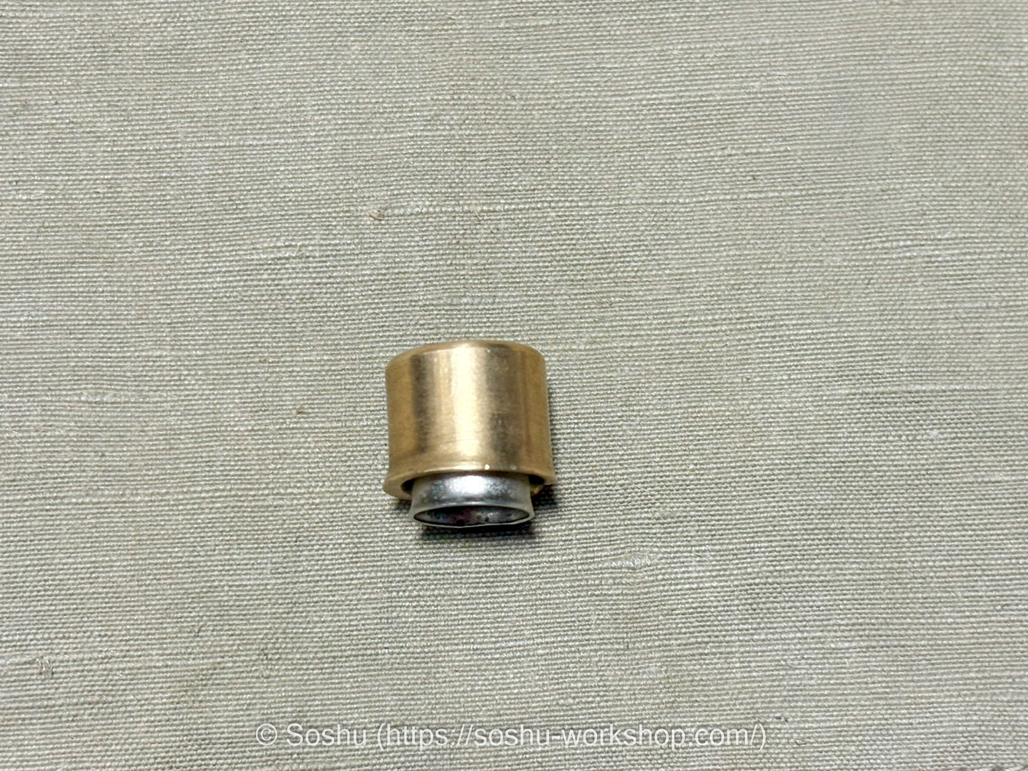
Before firing, the increaser tube rests on top of the support ear.
Upon firing, inertia causes the increaser tube to move downward, forcing the support ear into the interior of the increaser tube. The protrusions on the outer circumference of the support ear then catch on the increaser tube, locking the two together permanently.
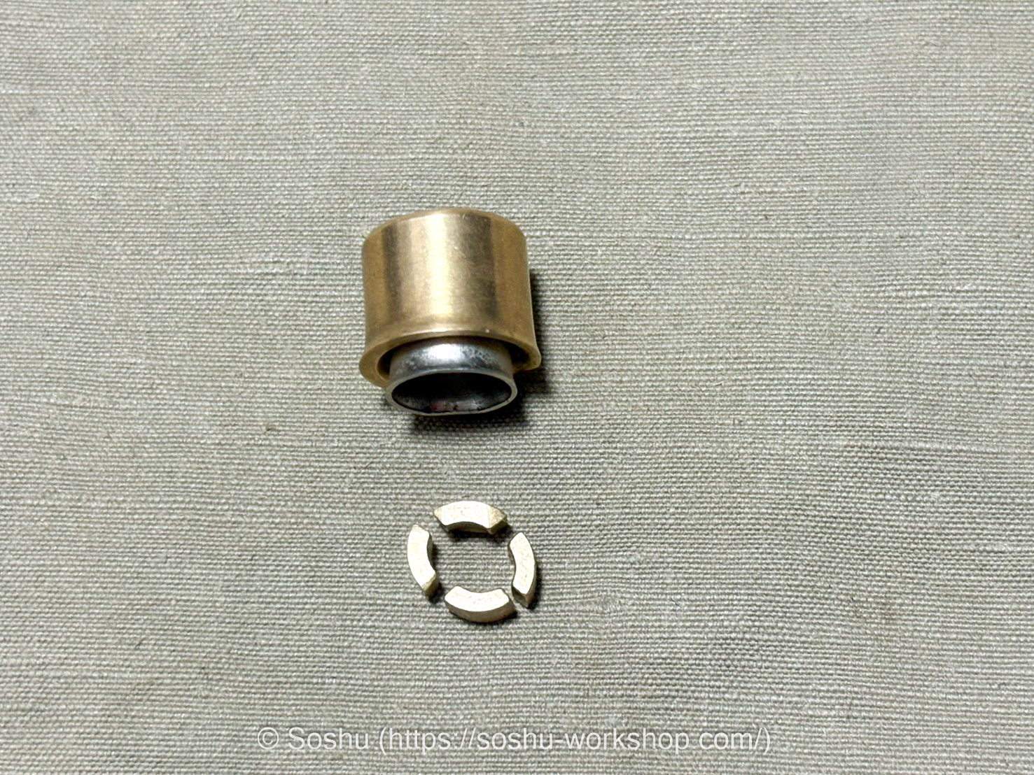
The compressed lower spring then extends, pushing the increaser tube and support ear upward. This releases the restraint on the centrifugal pieces, allowing them to move freely.
As the shell is imparted with spin by the rifling upon firing, the centrifugal force causes the four centrifugal pieces to fly outward.
With nothing left to restrain the firing pin, the shell is now in a state where the firing pin can strike the percussion cap upon impact with the target.
Finally, assembling the components into the fuze in order results in the configuration shown here.
Marking Band
The 1940 “Army Directive No. 3: Detailed Regulations for Ammunition Handling”3 is an extremely useful reference for researching ammunition such as artillery shells and small arms rounds.
Artillery shells are painted with band-shaped markings in colors such as red and yellow, and the meanings of these markings are summarized in Appendix Table 3 of this document. According to this, for standard artillery shells the type of round was indicated by a type marking applied to the center of the cylindrical section of the projectile.
The colors of the type markings applied to the center of artillery shells can be broadly summarized as follows.
| Round Type | Marking Color |
|---|---|
| High-explosive shell | Yellow |
| Cast iron high-explosive shell | Green |
| Shrapnel shell | Red |
| Armor-piercing shell | White |
| Tracer armor-piercing shell | Green and White |
| Tracer high-explosive shell | Green and Yellow |
| Practice round | No marking |
To elaborate, the cast iron high-explosive shell is a substitute for the standard shell, with the shell casing made from cast iron rather than steel. Cast iron is hard but brittle, meaning fragments produced upon detonation tend to be finer than those from a steel shell, which is considered a disadvantage in terms of lethal effectiveness.
The red band on the warhead is known as the “填薬標識” (explosive filling marking). This marking is applied to rounds that have been filled with an explosive charge. Hand grenades filled with explosive are also painted red on the head, which is considered to carry the same meaning.
Applying this standard, the example on loan from Dekunobo has a yellow marking band at the center, identifying it as a high-explosive shell. My two examples, on the other hand, show no central marking band, identifying them as practice rounds.
It should also be noted that all three examples introduced here show traces of red paint on the warhead, suggesting that all were at some point treated as rounds filled with an explosive charge. On the example with the expanded warhead, most of the paint has flaked off, but some red paint remains in places.
Type 94 Practice Round
The Type 94 Practice Round was a round standardized for peacetime training use with the Type 89 Heavy Grenade Discharger.
According to “Authorizing Provisional Standard for Alternative Ammunition for Model 94 Ammunition of Model 89 Grenade Launcher”4, the structure was identical to that of the Type 89 Mortar Shell, except that the lower portion of the bursting charge chamber was filled with sand and the upper portion with a small explosive bag. Ballistic performance was broadly comparable, and upon detonation it produced a “white flash”, designed to facilitate observation of the point of impact.
What follows is speculation, but taking into account the absence of any yellow markings, it seems likely that the example showing expansion and deformation of the warhead and upper body is a Type 94 Practice Round.
The Type 94 Practice Round was loaded with a small explosive charge in the warhead. As the deformation on this example is concentrated primarily around the warhead area, it is possible that the detonation of this charge blew the warhead off and separated it from the body.
When later reassembled as a souvenir or for storage, a warhead from a different example was used, resulting in a mismatch between the serial numbers on the warhead and body. This line of reasoning would provide a plausible explanation for both the deformation of the warhead and the mismatched markings.
While this example is generally considered to have been deformed by training use, it seems unlikely that the shock of firing alone would cause this degree of expansion in the warhead. It is more probable that pressure was applied from the inside by the action of the internal explosive charge.
Reference Drawings
Below I present the drawings related to the Type 89 Mortar Shell from “Reference on the Handling of Grenade Dischargers” compiled by the Army Infantry School. These are useful references for understanding the structure and operating principles of the shell.
First is the overall diagram of the Type 89 Mortar Shell. Throughout this article, the terminology used for each part follows the nomenclature shown in this diagram.
This is the drawing of the Type 88 Small Instantaneous Fuze. It contains detailed information on the names of each component and the operating mechanism, and the explanations of the fuze structure and operating principles in this article are based primarily on this drawing.

A drawing of a practice round was also included. The shape of the body differs somewhat from that of the Type 89 Mortar Shell, with the center of the base recessed so that the propellant cartridge extends into the interior of the body.
Furthermore, rather than expanding a copper driving band into the rifling using gas pressure as with the Type 89 Mortar Shell, it appears to have pre-formed protrusions known as “導子” (guide studs) for this purpose.
The fuze also appears to be a simplified design that merely replicates the external appearance of the functional fuze. Based on these points, this practice round appears to be a different type from the Type 94 Practice Round discussed earlier.
3D Data Creation
I also used a 3D scanner to capture the geometry of the Type 89 Mortar Shell. The scanner I use is the Revopoint Metro Y Pro, which can capture object geometry at a nominal accuracy of 0.01mm.
As it uses a blue laser, it can accurately capture data from metal and dark-colored objects. It is truly the perfect scanner for my purposes.
On the PC, the data is captured as a 3D model as shown here. Processing the data requires significant 3D computational performance, so a relatively high-spec PC is needed.
As the base cannot be captured in a single scan, it is scanned separately with the object repositioned and then merged in software afterward.
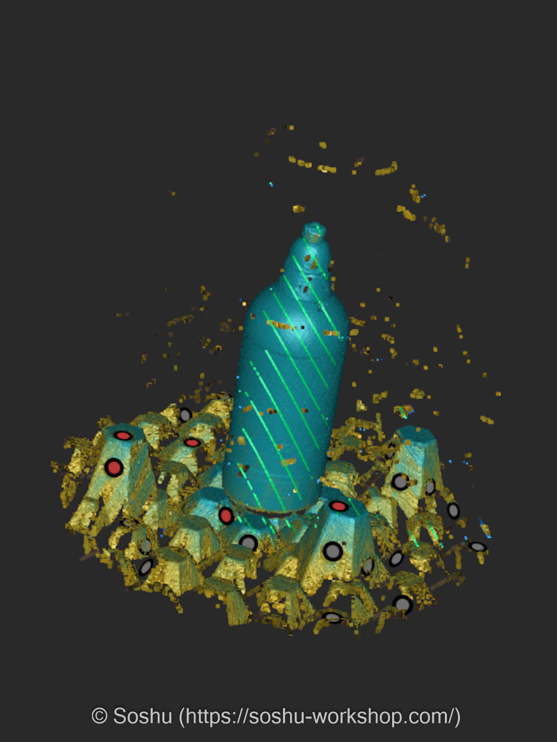
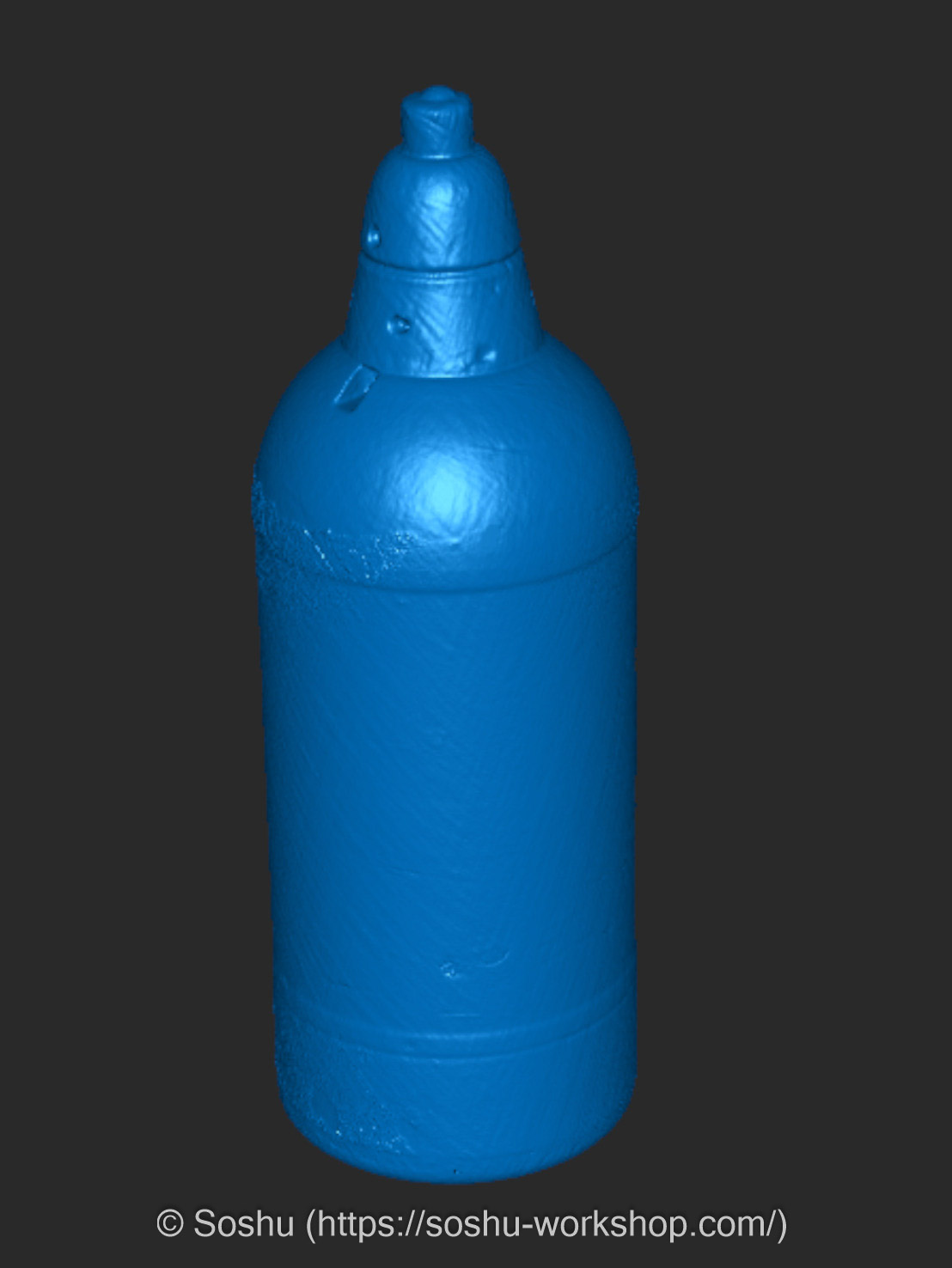
Here is the result after removing unnecessary data such as marker blocks and merging the scans taken from each direction. Fine details such as small holes and notches have been reproduced with considerable accuracy.
However, as the scan data contains minor noise and surface irregularities, it is not suitable as master data for 3D printing in its current state. I will therefore redesign the model from scratch in CAD, using the scan data as a reference.
I plan to commercialize this Type 89 Mortar Shell in the future. Having previously had model builds published in commercial magazines, I hope to draw on that experience to produce something with careful attention to surface texture and fine detail.
脚注
- “Establishment of interim standards of the 89-type heavy grenade dischargers and the 89-type shells as their ammunition” JACAR (Japan Center for Asian Historical Records) Ref.C01003949000, Mitsu Dainikki, Vol. 1, 1931 (National Institute for Defense Studies of the Ministry of Defense) ↩︎
- “Handling precautions of Model 88 small super quick fuse” JACAR (Japan Center for Asian Historical Records) Ref.C01001846900, Dainikki, Koshu, 1940 (National Institute for Defense Studies of the Ministry of Defense) ↩︎
- “Appendix 1 through Appendix 5” JACAR (Japan Center for Asian Historical Records) Ref.C14011063000, Army Directive No. 3: Detailed Regulations for Ammunition Handling, January 27, 1940 (National Institute for Defense Studies of the Ministry of Defense) ↩︎
- “Authorizing provisional standard for alternative ammunition for Model 94 ammunition of Model 89 grenade launcher” JACAR (Japan Center for Asian Historical Records) Ref.C01001503300, Dainikki, Koshu, 1937 (National Institute for Defense Studies of the Ministry of Defense) ↩︎